As networkers, we’re constantly thinking about redundancy and uptime. We’re taught that multiple links and devices means resiliency, which can be true, but complexity in the network can be equally complex to troubleshoot when things go wrong.
The classic Layer 1-2 redundancy model calls for multiple uplinks between hosts, switches, and routers. By making multiple paths available, you can create a fault-tolerant architecture. We usually need a protocol to protect against forwarding loops, which in Ethernet switching has traditionally been Spanning Tree (STP) and its variants. STP is one of those protocols that you can set and forget—until it’s time to troubleshoot.
So how do we as networkers continue to offer multiple links between devices and reduce the vulnerabilities of loop-free protocols like STP?
One option is to buy a single chassis-based Ethernet switch and load it up with redundant supervisors, line cards, and power supplies. This can be costly and often requires more cabinet space and power than is necessary.
Another option is switch stacking. A few years ago, switch vendors introduced stacking technology into certain switches. These switches have a stacking fabric that allows multiple independent devices to be configured as one virtual chassis. By connecting two standalone top-of-rack switches as one virtual chassis, we get the benefit of multiple line cards, redundant power, and a redundant control plane all in a smaller rack footprint than a bigger, chassis-based switch. What’s more, we get the added benefit of being able to fully utilize the extra capacity that we once stranded with STP and other active/standby techniques.
When host redundancy is a networking goal, the most common deployment that we see is switch stacking.
Stacking enables link aggregation between systems, which is very powerful in the network. Link aggregation gives you the ability to bond two or more physical links and present them as one logical aggregate link with the combined bandwidth of all members. On the server side of things, this can be called NIC teaming or bonding (bond mode 4 if you are a Linux user). On the routing and switching side, we specifically use Link Aggregation (IEEE 802.3ad), and often the LACP (Link Aggregation Control Protocol) option with it.
By deploying in a stacked environment with link aggregation, your server with 2x1G NICs can have 2 Gbps of active uplink capacity across two, physically diverse switches. Your switches can have that same redundancy for their uplink capacity. Your network can take full advantage of the extra capacity, and in the event of a failure, it automatically diverts traffic to remaining members.
Taking this a step further, we have server virtualization. It’s a fantastic tool, and redundancy is an important aspect.
As we combine more virtual hosts onto less hardware, the impact of an individual outage grows.
What we typically do here is follow the idea of link aggregation across multiple switches. We use the hypervisor’s virtual switch to again create an 802.3ad-bonded link. We like the idea of network separation by function, so we use VLAN trunking over the bundle between the switch fabric and hypervisor. That way, we can move individual subnets and virtual machines (VMs) as needed.
There are different ways to bond links on server hardware.
I often prefer to configure LACP when using link aggregation because an individual link member won’t begin to forward until LACP has negotiated its state. If one of your switches has link but isn’t ready to forward, and your server detects link on the individual member, the server might forward to an unready switch member. LACP can prevent this.
Despite its benefits, LACP isn’t appropriate for every aggregated Ethernet scenario.
If your link is saturated or your CPU resources prevent the LACP control packets from being generated, your physical link might drop because one end didn’t receive its PDUs within the configured interval.
Some hypervisors include LACP support, some make you pay for it, and some don’t support it at all.
Remember that LACP is an option inside of the 802.3ad protocol (the terms are often incorrectly used synonymously), so even if your equipment can’t support LACP, link aggregation may still be a great option for you.
It’s possible to mix switch types in order to create a custom stack to fit your particular needs.
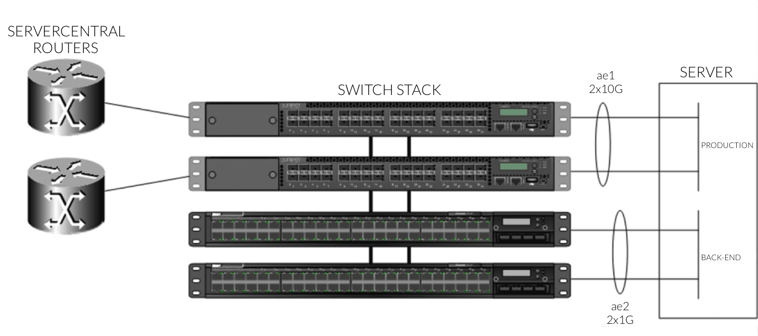
For example, you might have two 10-Gbps switches and two 1-Gbps switches in a single 4-member stack:
 Virtual Chassis with Link Aggregation
Here, your server has 20 Gbps of capacity for production traffic and 2 Gbps of capacity for back-end management connectivity. From a switch management standpoint, it’s one device with two logical links to configure.
Stackable switches with link aggregation provide a nice solution in the data center, where space is valuable and uptime is crucial.
Your specific configuration will depend on your hardware vendor, OS, and link capacity. Remember, we’re always here to talk through your options (whether you’re a managed network customer or not). If you need help, just ask!
